An UWB-based Indoor Positioning System Model and Applications
Junho Seo, Sungwon Lee, Yonghwan Jeong, Yeongjoon Bae, and Dongkyun Kim
School of Computer Science & Engineering, Kyungpook National University
80, Daehak-ro, Buk-gu
Daegu, Korea
{jhseo, swlee, yhjeong, yjbae}@monet.knu.ac.kr, dongkyun@knu.ac.kr
Abstract
With growing interest in LBS (Location Based Services), demand for LBS is increasing in the indoor environment. Since GPS (Global Positioning System) does not work in an indoor environment, IPS (Indoor Positioning System) is required, which is a positioning system specialized for an indoor environment. Although IPS using Wi-Fi, Bluetooth, RF, etc. have been studied, there are problems such as a large positioning error and a short communication distance. In this paper, we propose an IPS system model using UWB technology and present an example for applications in emergency and non-emergency situations.
Keywords- Location-Based-Service; Indoor Positioning System; Ultra-Wideband
1. Introduction
The importance of LBS (Location Based Service) is increasing [1]. Typically, there are many GPS(Global Positioning System)-based applications such as navigation, which are commonly used in vehicles. Recently, there is a demand for LBS in indoor environments such as buildings. For example, you can find out where you can get your desired items at a large mart or underground shopping mall, what route you need to go from your first visit to your destination, and where to escape if a disaster such as a fire occurs LBS can be utilized in the situation of. However, it is not suitable to use GPS in indoor environment because of satellite signal unreachability problem and intentional error in military reasons [2]. Therefore, it is necessary to use new location tracking technology specialized for indoor environment, and this is called an IPS (Indoor Positioning System). Various researches have been carried out for the IPS using Wi-Fi [3], Bluetooth [4], RF (Radio Frequency) [5] and UWB (Ultra-Wide band) [6].
For IPS, it is necessary to consider characteristics such as infrastructure cost, accuracy of location measurement, and reduction of communication distance due to complex indoor structure. First, Wi-Fi-based IPS [3] has a lot of public Wi-Fi APs, so it can provide location-based services at a relatively low cost. However, there is a relatively large difference in accuracy depending on the indoor structure, and since the positioning error is about 3 to 4 meters, it is somewhat difficult to provide an accurate position in the indoor environment. Bluetooth-based IPS [4] has advantages in terms of cost because multiple sensors can be deployed at low cost. However, this also has a positioning error of about 3 ~ 5meters like Wi-Fi. Since the signal strength is weak, the communication distance is as short as 30m and it is easily affected by obstacles. In the case of IPS [5] using RFID technology, the price of RFID tag is low, and the positioning error is only 0.1m, which is advantageous in that it has high accuracy. However, since the range of recognizing RFID tags is also narrow in units of 1 to 2 meters, there is a problem that an enormous amount of tags are required in a wide room such as a department store. These disadvantages are the obstacles to the development of indoor positioning applications.
UWB uses a wide band of 3.1 ~ 10.6GHz and is a technology capable of transmitting a large amount of information at a high transmission rate even at a low power. UWB has a low error rate of about 20cm in accuracy and has a high transmittance to obstacles such as walls. In addition, Wi-Fi and Bluetooth use the same ISM band, which can cause signal interference with each other. UWB, on the other hand, features very low spectral densities and short pulse widths, making it less susceptible to peripherals. Because of this characteristic of UWB, it is considered that it is better than the technologies mentioned in the previous paragraph in indoor environment requiring high accuracy and permeability to obstacles.
The following configuration is followed. In Section 2.1, we propose a system model to provide UWB-based IPS, and in Section 2.2, we describe the distance measurement technique to be used in UWB IPS system. In Section 2.3, we give some examples of applications that can use the proposed system model, and conclude in Section 3.
2. System Model
2.1. Proposed System Model
In this section, we propose IPS model that can support various applications (described in Section 2.3) by using devices equipped with UWB chipset. The system model proposed in this paper consists of at least 3 anchor nodes and 1 tag node. All the anchor nodes and the tag node includes UWB communication chipset and ARM processor. In addition, the tag node is connected to a device (android device) including input, control, and output units that can execute related applications as well as computing and memory unit via USB connection.
In the proposed system, each anchor nodes periodically broadcasts a Range Calculation Messages (RCMs) which contains corresponding information that the tag node can calculate its position. The RCM message is periodically transmitted of whether the tag node exists or not.
In addition, when UWB chipset of the tag node receives the RCM message from the surrounding anchor node, it transmits the received RCM message to the android device connected via USB connection. UWB. The android device that receives the RCM message from the UWB chipset of the tag node comprehend the sender ID of the newly received RCM message. If the RCM message transmitted from the sender node was received before, the profile information of stored anchor node is updated. However, if the RCM message transmitted from the new sender node, the profile information of the new anchor node is added to the table using corresponding RCM message.
The android device that maintains USB connection with the tag node repeats this process and counts the number of the anchor nodes that have sent an RCM message to itself. If the android device receives three different anchor nodes, it uses the profile information of the stored anchor terminal to estimate its location information as Section 2.2. Figure 1 illustrates this system.
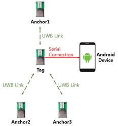
Figure 1. Proposed system model
Therefore, in the proposed IPS model, it is assumed that anchor nodes operate at the stationary position without mobility. Additionally, unlimited power is continuously supplied to anchor nodes. The tag node, on the other hand, are assumed to be mobility and connected to the android device that operate on limited battery. The android device not only run pre-installed applications, but also has sufficient computing ability and memory space. Moreover, it includes the ability to receive real-time data from an external server using LTE and wireless LAN.
2.2. Calculate Position of the Tag Node
The tag node measures and stores the distance between the tag node and anchor node whenever a new RCM message is received from the anchor node. The tag node uses ToF(Time-of-Flight) method to calculate distance between two nodes(the tag and the anchor).
In the RCM message periodically broadcasted from the anchor node, time information (Time-of-Departure, ToD) of the message transmission is recorded in the message. Therefore, at the time when tag node receives RCM message can recognize ToD information of RCM message. Also, the tag node acquires the time information (Time-of-Arrival, ToA) of the actual reception of the message from the UWB chipset. After obtaining the two time information, ToF can calculated by the following equation (1).
![]() (1)
(1)
The tag node that computes ToF from at least three different anchor nodes transmits the three ToF information estimated by itself to the connected android device using serial communication. When the android device receives these ToF information, it forward the information to the installed and running android application. The android application calculates the distance information from the three anchor nodes by using the trilateration method and calculates the location information of the tag node connected to the android device. The calculated location information is used as input for various indoor positioning related applications described in Section 2.3.
Therefore, it is essential to receive RCM messages transmitted from at least three different anchor nodes in order to estimate the position of tag node and support related applications. However, if all anchor nodes transmit RCM message at the same time with same period, the collision among RCM messages occurs which is unable to support the application ordinarily. So, anchor nodes avoid collisions of RCM messages by performing a backoff using jitter determined by their id value.
2.3. Application Examples of Proposed System Model
In the previous two sections, we introduced the IPS model to support applications based on IPS model and the coordinate computing function of the tag node. In this section, we categorize and introduce examples that can take advantage of these system and function.
IPS based applications mentioned in this paper can be categorize into emergency and non-emergency applications depending on the QoS(Quality of Service). In case of emergency applications, it has the purpose of minimizing the loss of property and life in the disaster such as a fire or an earthquake. In this case of disaster response coping application, the tag node proposed in this system is connected to android system of the robot which is input for the initial action in case of disaster. The android system receives the RCM message from the anchor installed in the building where the disaster occurred through the UWB chipset of the tag node and calculates its position. The location information is utilized in the following manner.
1) It collects its position and disaster situation information at the same time and uses it as basic data to determine the priority of rescue activities
2) In case that it is difficult or impossible to enter a location where structural activities are required due to unpredictable obstacles, a dynamic structural plan is established by utilizing its own location information and indoor structure information
3) If the robot alone can not perform sufficient disaster response(rescue activities), it will improve the efficiency of rescue activities by specifying the exact location to request additional robot and manpower dispatch
4) Log the indoor location information measured by the robot during disaster response. By analyzing the log after the completion of all the rescue activities, the rescue movement of the robot and the time consumed in the rescue activities are analyzed to utilize the rescue robot as the base information for upgrading the system performance of the rescue robot
Meanwhile, in the case of non-emergency applications, it has the purpose of providing various convenience to people who have activities in a wide infrastructure such as a hospital or a department store. The tag node proposed in this system is connected to android device of the people when they enter to the infrastructure. The android device receives the RCM message from the anchor which deployed widely in the building through the UWB chipset of the tag node and calculates its position. The location information is utilized in the following manner.
1) The user of this application is able to search for the desired destination. The application provides the route to the corresponding destination based on the current location information of the user.
2) It keeps track of the position of children who are active, so parents can prevent the situation that of missing child. Even though when the parents recognizes their child are missing, they can find the location of children using application without being embarrassed.
3) The application is applied to smart building where the light is turned on automatically by the user’s location and direction information. In addition, the light is automatically turned off after the user passes.
3. Conclusion
In this paper, we propose a system model to provide UWB-based IPS. The system model proposed in this paper consists of at least 3 anchor nodes, 1 tag node and android device. All the anchor nodes and the tag node includes UWB communication chipset and ARM processor. The tag node computes ToF through the RCM message broadcast periodically from the anchor node and sends the ToF information to the connected android device via USB serial connection. The android device estimates the location of the tag with ToF received from tag and the predefined corresponding anchor coordinate. In addition, we discussed the applications that can utilize the estimated location coordinate of the tag into emergency and non-emergency situations.
In the future, we will implement the proposed system model directly and analyze system performance in various indoor environments.
References
[1] H. Liu, H. Darabi, P. Banerjee, and J. Liu, "Survey of wireless indoor positioning techniques and systems," IEEE Transactions on Systems, Man, and Cybernetics, Part C: Applications and Reviews, vol. 37, no. 6, pp. 1067-1080. Nov. 2007.
[2] Yassin, A., Nasser, Y., Awad, M., Al-Dubai, A., Liu, R., Yuen, C., ... & Aboutanios, E. (2016). Recent advances in indoor localization: A survey on theoretical approaches and applications. IEEE Communications Surveys & Tutorials, 19(2), 1327-1346.
[3] Y. Zhuang, Z. Syed, J. Georgy, N. El-Sheimy, Autonomous smartphone-based WiFi positioning system by using access points localization and crowdsourcing, Pervasive and Mobile Computing, Volume 18, 2015, Pages 118-136
[4] X. Lin, T. Ho, C. Fang, Z. Yen, B. Yang and F. Lai, "A mobile indoor positioning system based on iBeacon technology," 2015 37th Annual International Conference of the IEEE Engineering in Medicine and Biology Society (EMBC), Milan, 2015, pp. 4970-4973.
[5] S. S. Saab and Z. S. Nakad, "A Standalone RFID Indoor Positioning System Using Passive Tags," in IEEE Transactions on Industrial Electronics, vol. 58, no. 5, pp. 1961-1970, May 2011.
[6] M. Kok, J. D. Hol and T. B. Schön, "Indoor Positioning Using Ultrawideband and Inertial Measurements," in IEEE Transactions on Vehicular Technology, vol. 64, no. 4, pp. 1293-1303, April 2015.